Extrusion
Overview
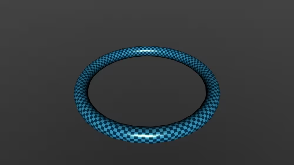
Extrusion is a geometry node that sequentially stretches a 2D cross section along a 3D-spine path in the local coordinate system, creating an outer hull. Scaling and rotating the crossSection 2D outline at each control point can modify the outer hull of the Extrusion to produce a wide variety of interesting shapes.
The Extrusion node belongs to the Geometry3D component and requires at least support level 4, its default container field is geometry. It is available since VRML 2.0 and from X3D version 3.0 or higher.
Hierarchy
1
2
3
+ X3DNode
  + X3DGeometryNode
    + Extrusion
Fields
| Type | Access Type | Name | Default Value |
|---|---|---|---|
| SFNode | [in, out] | metadata | NULL |
| MFVec2f | [in] | set_crossSection | |
| MFRotation | [in] | set_orientation | |
| MFVec2f | [in] | set_scale | |
| MFVec3f | [in] | set_spine | |
| SFBool | [ ] | beginCap | TRUE |
| SFBool | [ ] | endCap | TRUE |
| SFBool | [ ] | solid | TRUE |
| SFBool | [ ] | ccw | TRUE |
| SFBool | [ ] | convex | TRUE |
| SFFloat | [ ] | creaseAngle | 0 |
| MFVec2f | [ ] | crossSection | [ 1 1, 1 -1, -1 -1, -1 1, 1 1 ] |
| MFRotation | [ ] | orientation | 0 0 1 0 |
| MFVec2f | [ ] | scale | 1 1 |
| MFVec3f | [ ] | spine | [ 0 0 0, 0 1 0 ] |
SFNode [in, out] metadata NULL [X3DMetadataObject]
Information about this node can be contained in a MetadataBoolean, MetadataDouble, MetadataFloat, MetadataInteger, MetadataString or MetadataSet node.
Hint
MFVec2f [in] set_crossSection (-∞,∞)
The crossSection array defines a silhouette outline of the outer Extrusion surface. crossSection is an ordered set of 2D points that draw a piecewise-linear curve which is extruded to form a series of connected vertices.
Hint
- This field is not accessType inputOutput since X3D browsers might use different underlying geometric representations for high-performance rendering, and so output events are not appropriate.
Warnings
- If the order of crossSection point definition does not match clockwise/counterclockwise setting of ccw field, then self-intersecting, impossible or inverted geometry can result!
- It is an error to define this transient inputOnly field in an X3D file, instead only use it a destination for ROUTE events.
MFRotation [in] set_orientation [-1,1] or (-∞,∞)
The orientation array is a list of axis-angle 4-tuple values applied at each spine-aligned cross-section plane.
Hints
- If the orientation array contains a single 4-tuple value, it is applied at all spine-aligned crossSection planes.
- Number of values must all match for 3-tuple spine points, 2-tuple scale values, and 4-tuple orientation values.
- This field is not accessType inputOutput since X3D browsers might use different underlying geometric representations for high-performance rendering, and so output events are not appropriate.
Warning
- It is an error to define this transient inputOnly field in an X3D file, instead only use it a destination for ROUTE events.
MFVec2f [in] set_scale (0,∞)
scale is a list of 2D-scale parameters applied at each spine-aligned cross-section plane.
Hints
- Number of values must all match for 3-tuple spine points, 2-tuple scale values, and 4-tuple orientation values.
- This field is not accessType inputOutput since X3D browsers might use different underlying geometric representations for high-performance rendering, and so output events are not appropriate.
Warnings
- Zero or negative scale values not allowed.
- It is an error to define this transient inputOnly field in an X3D file, instead only use it a destination for ROUTE events.
MFVec3f [in] set_spine (-∞,∞)
The spine array defines a center-line sequence of 3D points that define a piecewise-linear curve forming a series of connected vertices. The spine is set of points along which a 2D crossSection is extruded, scaled and oriented.
Hints
- The spine array can be open or closed (closed means that endpoints are coincident).
- Number of values must all match for 3-tuple spine points, 2-tuple scale values, and 4-tuple orientation values.
- This field is not accessType inputOutput since X3D browsers might use different underlying geometric representations for high-performance rendering, and so output events are not appropriate.
Warnings
- Special care is needed if creating loops or spirals since self-intersecting, impossible or inverted geometry can result!
- It is an error to define this transient inputOnly field in an X3D file, instead only use it a destination for ROUTE events.
SFBool [ ] beginCap TRUE
Whether beginning cap is drawn (similar to Cylinder top cap).
Warning
- Since this field has accessType initializeOnly, the value cannot be changed after initial creation.
SFBool [ ] endCap TRUE
Whether end cap is drawn (similar to Cylinder bottom cap).
Warning
- Since this field has accessType initializeOnly, the value cannot be changed after initial creation.
SFBool [ ] solid TRUE
Setting solid true means draw only one side of polygons (backface culling on), setting solid false means draw both sides of polygons (backface culling off).
Hints
- Mnemonic “this geometry is solid like a brick” (you don’t render the inside of a brick).
- If in doubt, use solid=’false’ for maximum visibility.
- AccessType relaxed to inputOutput in order to support animation and visualization.
Warning
- Default value true can completely hide geometry if viewed from wrong side!
SFBool [ ] ccw TRUE
The ccw field indicates counterclockwise ordering of vertex-coordinates orientation.
Hints
- A good debugging technique for problematic polygons is to try changing the value of ccw, which can reverse solid effects (single-sided backface culling) and normal-vector direction.
- Clockwise
Warning
- Consistent and correct ordering of left-handed or right-handed point sequences is important throughout the coord array of point values.
SFBool [ ] convex TRUE
The convex field is a hint to renderers whether all polygons in a shape are convex (true), or possibly concave (false). A convex polygon is planar, does not intersect itself, and has all interior angles < 180 degrees.
Hints
- Concave is the opposite of convex.
- Select convex=false (i.e. concave) and solid=false (i.e. two-sided display) for greatest visibility of geometry.
- convex polygon
- Tessellation
Warning
- Concave or inverted geometry may be invisible when using default value convex=true, since some renderers use more-efficient algorithms to perform tessellation that may inadvertently fail on concave geometry.
SFFloat [ ] creaseAngle 0 [0,∞)
creaseAngle defines angle (in radians) where adjacent polygons are drawn with sharp edges or smooth shading. If angle between normals of two adjacent polygons is less than creaseAngle, smooth shading is rendered across the shared line segment.
Hints
- creaseAngle=0 means render all edges sharply, creaseAngle=3.14159 means render all edges smoothly.
- Radian units for angular measure
MFVec2f [ ] crossSection [ 1 1, 1 -1, -1 -1, -1 1, 1 1 ] (-∞,∞)
The crossSection array defines a silhouette outline of the outer Extrusion surface. crossSection is an ordered set of 2D points that draw a piecewise-linear curve which is extruded to form a series of connected vertices.
Hints
- The crossSection array can be open or closed (closed means that endpoints are coincident).
- Number of values must all match for 3-tuple spine points, 2-tuple scale values, and 4-tuple orientation values.
Warnings
- If the order of crossSection point definition does not match clockwise/counterclockwise setting of ccw field, then self-intersecting, impossible or inverted geometry can result!
- Avoid self-intersecting polygon line segments, otherwise defined geometry is irregular and rendering results are undefined (especially for end caps).
MFRotation [ ] orientation 0 0 1 0 [-1,1] or (-∞,∞)
The orientation array is a list of axis-angle 4-tuple values applied at each spine-aligned cross-section plane.
Hints
- If the orientation array contains a single 4-tuple value, it is applied at all spine-aligned crossSection planes.
- Number of values must all match for 3-tuple spine points, 2-tuple scale values, and 4-tuple orientation values.
MFVec2f [ ] scale 1 1 (0,∞)
scale is a list of 2D-scale parameters applied at each spine-aligned cross-section plane.
Hints
- Number of values must all match for 3-tuple spine points, 2-tuple scale values, and 4-tuple orientation values.
- If the scale array contains one value, it is applied at all spine-aligned crossSection planes.
Warning
- Zero or negative scale values not allowed.
MFVec3f [ ] spine [ 0 0 0, 0 1 0 ] (-∞,∞)
The spine array defines a center-line sequence of 3D points that define a piecewise-linear curve forming a series of connected vertices. The spine is set of points along which a 2D crossSection is extruded, scaled and oriented.
Hints
- The spine array can be open or closed (closed means that endpoints are coincident).
- Number of values must all match for 3-tuple spine points, 2-tuple scale values, and 4-tuple orientation values.
- If a spine is closed (or nearly closed) then the inner diameter usually needs to be greater than the corresponding crossSection width.
Warnings
- Special care is needed if creating loops or spirals since self-intersecting, impossible or inverted geometry can result!
- Ensure that spine segments have non-zero length and are not coincident with each other.
Advice
Hints
- Extrusion
- Insert a Shape node before adding geometry or Appearance.
Warning
- Take care to avoid defining parameter combinations that create self-intersecting, impossible or inverted geometry.
Example
Browser Compatibility
| Castle Game Engine | FreeWRL | X_ITE X3D Browser | X3D-Edit | X3DOM |
|---|---|---|---|---|