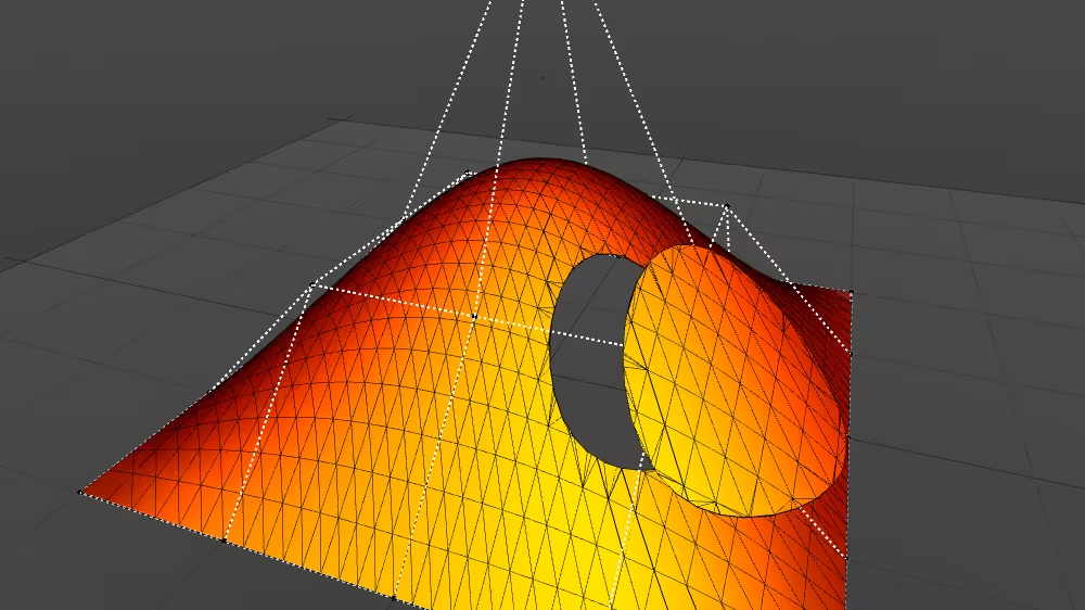
NurbsTrimmedSurface
Overview
NurbsTrimmedSurface generates texture coordinates from a Non-Uniform Rational B-Spline (NURBS) surface.
The NurbsTrimmedSurface node belongs to the NURBS component and requires at least support level 4, its default container field is geometry. It is available from X3D version 3.0 or higher.
Hierarchy
1
2
3
4
5
+ X3DNode
  + X3DGeometryNode
    + X3DParametricGeometryNode
      + X3DNurbsSurfaceGeometryNode
        + NurbsTrimmedSurface
Fields
| Type | Access Type | Name | Default Value |
|---|---|---|---|
| SFNode | [in, out] | metadata | NULL |
| SFInt32 | [in, out] | uTessellation | 0 |
| SFInt32 | [in, out] | vTessellation | 0 |
| SFBool | [ ] | solid | TRUE |
| SFBool | [ ] | uClosed | FALSE |
| SFBool | [ ] | vClosed | FALSE |
| SFInt32 | [ ] | uOrder | 3 |
| SFInt32 | [ ] | vOrder | 3 |
| SFInt32 | [ ] | uDimension | 0 |
| SFInt32 | [ ] | vDimension | 0 |
| MFDouble | [ ] | uKnot | [ ] |
| MFDouble | [ ] | vKnot | [ ] |
| MFDouble | [in, out] | weight | [ ] |
| SFNode | [in, out] | texCoord | NULL |
| SFNode | [in, out] | controlPoint | NULL |
| MFNode | [in] | addTrimmingContour | |
| MFNode | [in] | removeTrimmingContour | |
| MFNode | [in, out] | trimmingContour | [ ] |
SFNode [in, out] metadata NULL [X3DMetadataObject]
Information about this node can be contained in a MetadataBoolean, MetadataDouble, MetadataFloat, MetadataInteger, MetadataString or MetadataSet node.
Hint
SFInt32 [in, out] uTessellation 0 (-∞,∞)
Hint for surface tessellation.
SFInt32 [in, out] vTessellation 0 (-∞,∞)
Hint for surface tessellation.
SFBool [ ] solid TRUE
Setting solid true means draw only one side of polygons (backface culling on), setting solid false means draw both sides of polygons (backface culling off).
Hints
- Mnemonic “this geometry is solid like a brick” (you don’t render the inside of a brick).
- If in doubt, use solid=’false’ for maximum visibility.
- AccessType relaxed to inputOutput in order to support animation and visualization.
Warning
- Default value true can completely hide geometry if viewed from wrong side!
SFBool [ ] uClosed FALSE
Whether opposite surface sides are closed (seamless) across u dimension.
SFBool [ ] vClosed FALSE
Whether opposite surface sides are closed (seamless) across u dimension.
SFInt32 [ ] uOrder 3 [2,∞)
Define order of surface by polynomials of degree = order-1.
SFInt32 [ ] vOrder 3 [2,∞)
Define order of surface by polynomials of degree = order-1.
SFInt32 [ ] uDimension 0 [0,∞)
Number of control points in u dimension.
SFInt32 [ ] vDimension 0 [0,∞)
Number of control points in v dimension.
MFDouble [ ] uKnot [ ] (-∞,∞)
Knot vector, where size = number of control points + order of curve.
MFDouble [ ] vKnot [ ] (-∞,∞)
Knot vector, where size = number of control points + order of curve.
MFDouble [in, out] weight [ ] (0,∞)
Vector assigning relative weight value to each control point.
SFNode [in, out] texCoord NULL [X3DTextureCoordinateNode|NurbsTextureCoordinate]
Optional single contained NurbsTextureCoordinate, TextureCoordinate, TextureCoordinateGenerator or MultiTextureCoordinate node that can specify coordinates for texture mapping onto corresponding geometry.
SFNode [in, out] controlPoint NULL [X3DCoordinateNode]
Optional single contained Coordinate or CoordinateDouble node that can specify control points for NURBS geometry definitions.
MFNode [in] addTrimmingContour
Input field addTrimmingContour.
MFNode [in] removeTrimmingContour
Input field removeTrimmingContour.
MFNode [in, out] trimmingContour [ ] [Contour2D]
A set of Contour2D nodes are used as trimming loops.
Hint
- If no trimming contours are defined, NurbsTrimmedSurface has same semantics as NurbsPatchSurface node.
Example
