Transform
Overview
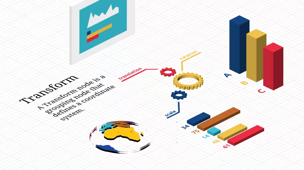
Transform is a Grouping node that can contain most nodes. Transform translates, orients and scales child geometry within the local world coordinate system.
The Transform node belongs to the Grouping component and requires at least support level 1, its default container field is children. It is available since VRML 2.0 and from X3D version 3.0 or higher.
Hierarchy
1
2
3
4
+ X3DNode
  + X3DChildNode
    + X3DGroupingNode (X3DBoundedObject)*
      + Transform
* Derived from multiple interfaces.
Fields
| Type | Access Type | Name | Default Value |
|---|---|---|---|
| SFNode | [in, out] | metadata | NULL |
| SFVec3f | [in, out] | translation | 0 0 0 |
| SFRotation | [in, out] | rotation | 0 0 1 0 |
| SFVec3f | [in, out] | scale | 1 1 1 |
| SFRotation | [in, out] | scaleOrientation | 0 0 1 0 |
| SFVec3f | [in, out] | center | 0 0 0 |
| SFBool | [in, out] | visible | TRUE |
| SFBool | [in, out] | bboxDisplay | FALSE |
| SFVec3f | [ ] | bboxSize | -1 -1 -1 |
| SFVec3f | [ ] | bboxCenter | 0 0 0 |
| MFNode | [in] | addChildren | |
| MFNode | [in] | removeChildren | |
| MFNode | [in, out] | children | [ ] |
SFNode [in, out] metadata NULL [X3DMetadataObject]
Information about this node can be contained in a MetadataBoolean, MetadataDouble, MetadataFloat, MetadataInteger, MetadataString or MetadataSet node.
Hint
SFVec3f [in, out] translation 0 0 0 (-∞,∞)
Position (x, y, z in meters) of children relative to local coordinate system.
Hint
- The order of operation is first apply the center offset, then scaleOrientation and scale, then rotation, then restore the center offset, then translation.
SFRotation [in, out] rotation 0 0 1 0 [-1,1] or (-∞,∞)
Orientation (axis, angle in radians) of children relative to local coordinate system.
Hint
- The order of operation is first apply the center offset, then scaleOrientation and scale, then rotation, then restore the center offset, then translation.
SFVec3f [in, out] scale 1 1 1 (-∞,∞)
Non-uniform x-y-z scale of child coordinate system, adjusted by center and scaleOrientation.
Hints
- The order of operation is first apply the center offset, then scaleOrientation and scale, then rotation, then restore the center offset, then translation.
- Negative scale values allowed beginning with X3D version 3.1
SFRotation [in, out] scaleOrientation 0 0 1 0 [-1,1] or (-∞,∞)
Preliminary rotation of coordinate system before scaling (to allow scaling around arbitrary orientations).
Hint
- The order of operation is first apply the center offset, then scaleOrientation and scale, then rotation, then restore the center offset, then translation.
SFVec3f [in, out] center 0 0 0 (-∞,∞)
Translation offset from origin of local coordinate system, applied prior to rotation or scaling.
Hint
- The order of operation is first apply the center offset, then scaleOrientation and scale, then rotation, then restore the center offset, then translation.
SFBool [in, out] visible TRUE
Whether or not renderable content within this node is visually displayed.
Hints
- The visible field has no effect on animation behaviors, event passing or other non-visual characteristics.
- Content must be visible to be collidable and to be pickable.
SFBool [in, out] bboxDisplay FALSE
Whether to display bounding box for associated geometry, aligned with world coordinates.
Hint
- The bounding box is displayed regardless of whether contained content is visible.
SFVec3f [ ] bboxSize -1 -1 -1 [0,∞) or −1 −1 −1
Bounding box size is usually omitted, and can easily be calculated automatically by an X3D player at scene-loading time with minimal computational cost. Bounding box size can also be defined as an optional authoring hint that suggests an optimization or constraint.
Hints
- Can be useful for collision computations or inverse-kinematics (IK) engines.
- Precomputation and inclusion of bounding box information can speed up the initialization of large detailed models, with a corresponding cost of increased file size.
- X3D Architecture, 10.2.2 Bounding boxes
- X3D Architecture, 10.3.1 X3DBoundedObject
SFVec3f [ ] bboxCenter 0 0 0 (-∞,∞)
Bounding box center accompanies bboxSize and provides an optional hint for bounding box position offset from origin of local coordinate system.
Hints
- Precomputation and inclusion of bounding box information can speed up the initialization of large detailed models, with a corresponding cost of increased file size.
- X3D Architecture, 10.2.2 Bounding boxes
- X3D Architecture, 10.3.1 X3DBoundedObject
MFNode [in] addChildren
Input field addChildren.
MFNode [in] removeChildren
Input field removeChildren.
MFNode [in, out] children [ ] [X3DChildNode]
Grouping nodes contain an ordered list of children nodes.
Hints
- Each grouping node defines a coordinate space for its children, relative to the coordinate space of its parent node. Thus transformations accumulate down the scene graph hierarchy.
- InputOnly MFNode addChildren field can append new X3DChildNode nodes via a ROUTE connection, duplicate input nodes (i.e. matching DEF, USE values) are ignored.
- InputOnly MFNode removeChildren field can remove nodes from the children list, unrecognized input nodes (i.e. nonmatching DEF, USE values) are ignored.
- X3D Architecture 10.2.1 Grouping and children node types
Advice
Hints
- Each transformation creates a new coordinate system relative to the parent coordinate system.
- +Y axis is the up direction. (Similarly some scenes may consider +X is North and +Z is East.)
- Best authoring approach is to keep +Y axis pointing towards local up direction, supporting scene composability and effective navigation response (which is based on gravity direction).
- Insert a Shape node before adding geometry or Appearance.
- Translation/rotation/scaling field attributes can be defined in any order in the scene. The applied order of translation/rotation/scaling transformation-matrix operations remains consistent.
- Authors can modify order of translation/rotation/scaling operations by splitting them into separate nested parent/child Transform nodes.
- X3D Scene Authoring Hints, Coordinate Systems
- X3D Scene Authoring Hints, Scale Factors and Unit Conversions
- Apply
containerField='shape'if parent node is CADFace.
Warning
Example
Browser Compatibility
| Castle Game Engine | FreeWRL | X_ITE X3D Browser | X3D-Edit | X3DOM |
|---|---|---|---|---|